Lionel Electric Trains Identification Guide Sub-Title
These pages are best viewed at 1024 x 768 x 32 bit monitor resolution
Bottom of Page

This Identification Guide for Lionel Electric Trains covers the "Post-war Era" only from 1945 until 1969.

black horizontal bar

Lionel Trains Rotating Radar Antenna 
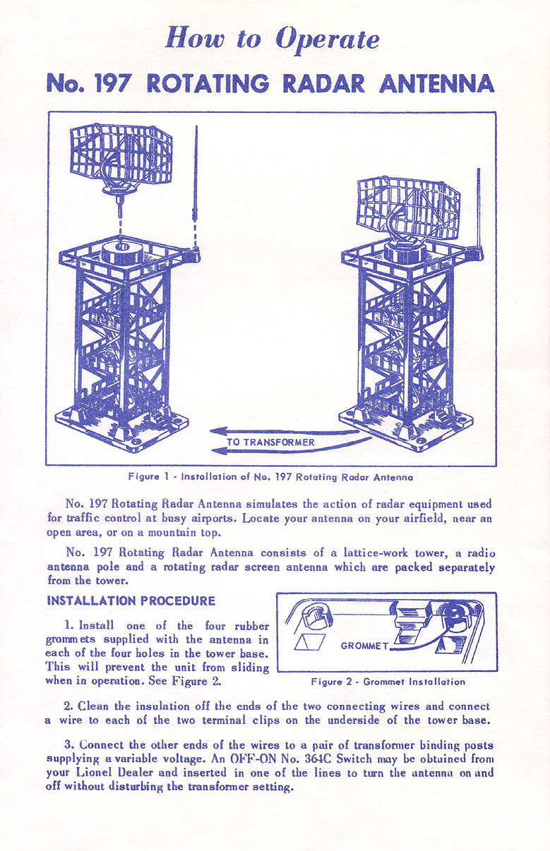
LIONEL TRAINS ROTATING RADAR ANTENNA No. 197

black horizontal bar

Lionel Trains Rotatating Radar Antenna No. 197 Variation A

Lionel Trains Rotating Radar AntennaThe Rotating Radar Antenna No. 197 was made from 1957 until 1959. The radar antenna would rotate when the vibrator beneath it at the top of the tower was activated. Made with a GRAY plastic base and BLACK frame, "LIONEL" in raised ORANGE letters on two sides, and a SILVER and BLACK antenna. There are two binding clips on the bottom for electrical connection.

No. 197-75 Box End

Lionel offered the radar head for separate sale under the No. 197-75. This radar tower is difficult to find in unbroken condition. The hand rails are often broken, and the radio antenna at the top is often missing or it is broken. Operators should note that it is sometimes difficult to get the antenna to rotate properly.
spacer
The base and lower structure of this tower was also used on the No. 175 Rocket Launcher and the No. 192 Operating Control Tower.
spacer
There are two variations:

No. 197 Late Classic Box End

Variation A: with a GRAY top railing. Came with a DULL SILVER painted radar head. Since these radar heads are easily changed these variations are not dated by this feature. Late 1957 to 1959 production.
spacer
Variation B: with an ORANGE top railing. Usually came with a BRIGHT SILVER CHROME finished radar head. Early 1957 production that is harder to find.

Towers that were available in 1957 came in a Late Classic Box (Part No. 197-32), while those sold later used the first of the Display Boxes (Part No. 197-45).
spacer
There are two instruction sheet that were produced both are numbered 197-31. The first was printed with DARK BLUE ink on WHITE paper and was dated 9-57 and was 6-1/2" by 9-1/2". A picture of the front page of this instruction sheet is shown below and the rear page is here. The second used BLUE ink on WHITE paper and is dated 6-58. This second printing was somewhat smaller at 5-1/2" by 8-1/2".

Dimensions: 12 inches high, 3 by 4-1/2 inch base.
spacer
Of note are the two changes that were made to the 6-58 Instruction sheet:
spacer
  1. Lionel informed the purchaser that the slot in the foot grommets was not centered and that these grommet should be inserted in the base with the grommet offset in the same direction to insure that the tower was level.
spacer
  2. The text "NOTE: Please disregard the "driving slug" listed on the envelope. This part has already been assembled into the mechanism at the factory" was removed from this instruction sheet. No. 197-30 Envelopes from late 1957 show the entry "1 No. 197-12 DRIVING SLUG" blacked out.
spacer

No. 197-30 Parts Envelope
spacer


spacer

Return To Previous Page

BB Home BB Privacy BB Legal BB Search BB Site Map BB Contact BB
Copyright Tandem Associates LLC Labeled with ICRA Top of Page