Lionel Electric Trains Identification Guide Sub-Title
These pages are best viewed at 1024 x 768 x 32 bit monitor resolution
Bottom of Page

This Identification Guide for Lionel Electric Trains covers the "Post-war Era" only from 1945 until 1969.

black horizontal bar

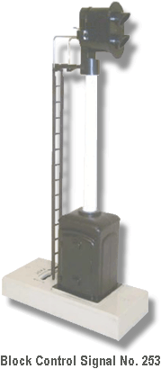
Lionel Trains Block Signal No. 153 LIONEL TRAINS BLOCK CONTROL SIGNAL No. 253

black horizontal bar

Block Control Signal No. 253 Variation A

Lionel Trains Block Signal No. 253The Block Control Signal No. 253 performed the same function as the No. 115 and No. 132 Stations in that it had the ability to stop a train for a limited amount of time usually in front of a station. This was accomplished with the use of a bimetallic strip that when current passed through it the heat generated would cause the these metal strips to separate thereby breaking the electrical connection. When hooked up to an insulated center rail block section of track the train would stop in this section until the heat dissipated and the connection was restored to the train. Although it is possible to stop the train without causing the directional unit on the engine to cycle (usually current must be maintained at about six volts), most operators just move the directional lever on the engine so that it only goes in the forward direction.
spacer
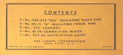
Included in the parts envelope No. 253-44 were two insulating pins for O Gauge and O27 Gauge track to establish and insulated block section in addition to lockons and connecting wires. A picture of this envelope is shown below.
spacer
This signal can be set so that the trains never stop by moving the lever on the signal that is just behind the ladder to the "CONT" (continuous) position. By moving the lever towards the "SLOW" position causes the engine to stop for different periods of time.
spacer
The signal head lamp cover (Part No. 450-13) is identical to the type that were used on the No. 450 Signal Bridge and the No. 452 Gantry Signal.

First produced in 1956, the No. 253 would be the first accessory to use the new two pin lamps. The only voltage available for these lamps, No. L12(R) and No. L12(G), in 1956 was rated at 6 to 8 volts. To operate these lamps a resistor was needed to drop the normal track voltage from 12 to 16 volts. This is the only accessory that used these lamps.
spacer
By 1957, when a 14 volt version of these lamps was available, all of the No. 253 Block Signals produced after 1956 used No. L19(R) and No. L19(G) lamps.

No. 253-44 Parts Envelope

Concerning the replacement of lamps on those signals made in 1956 the Lionel Service Manual dated 3-58 relate that: "If 14 volt lamps are used the resistor can be bypassed or eliminated." Lionel would continue to produce this block signal with the 14 volt lamps until the end of production in 1959.
spacer
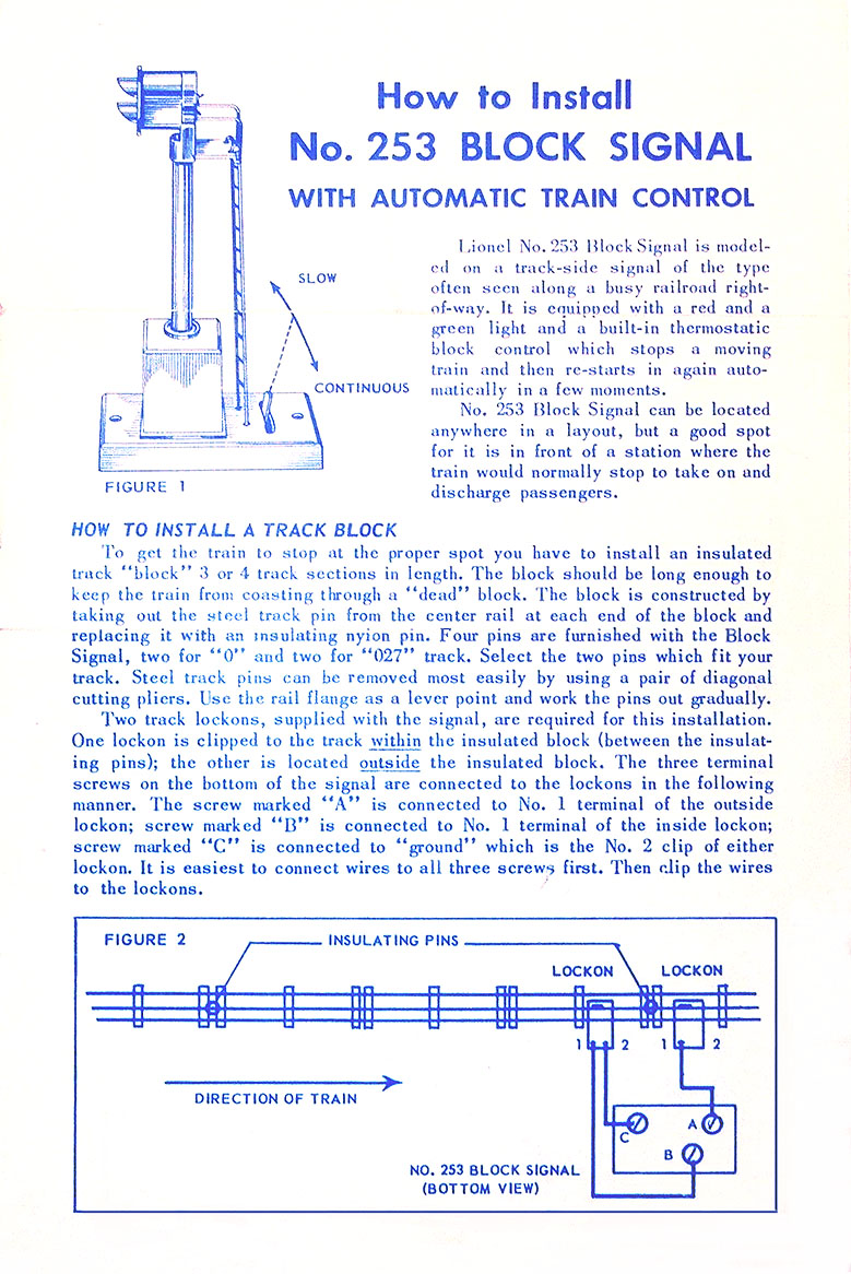
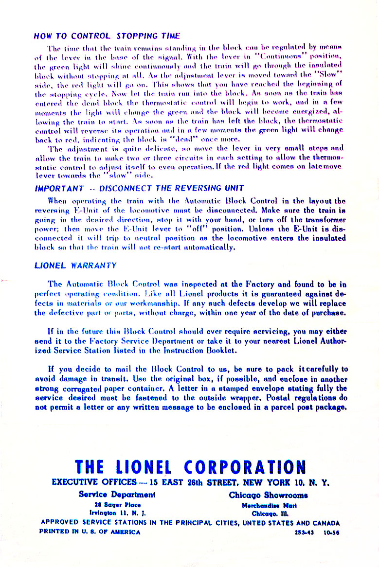
Two instruction sheets were issued under the number 253-43. The first dated 10-56 used BLUE ink on WHITE paper. This instruction sheet is shown below. The second instruction sheet was dated 3-57 used BLACK ink on YELLOW paper. The latter issue took issue with how to establish an insulated block section on the new Super-O track that was released in 1957.
spacer
The earliest production of this block signal had the control box portion of the base painted BLACK. Later editions, in what was obviously a cost cutting measure, would not be painted and were solid beige colored plastic. There are two variations:
spacer
Variation A: Has a BLACK painted signal control box on the base. The earliest production.
spacer
Variation B: The base is unpainted beige plastic.
spacer
Dimensions: 7" high, base: 4" long x 2" wide.

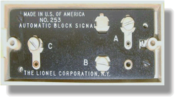
Bottom Veiw of the No. 253 Block Signal
spacer
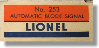
No. 253 Box End
spacer
Front Page of No. 253-43 Instruction Sheet Dated 10-56
spacer
Back Page of No. 253-43 Instruction Sheet Dated 10-56
spacer
Return To Previous Page

BB Home BB Privacy BB Legal BB Search BB Site Map BB Contact BB
Copyright Tandem Associates LLC Labeled with ICRA Top of Page