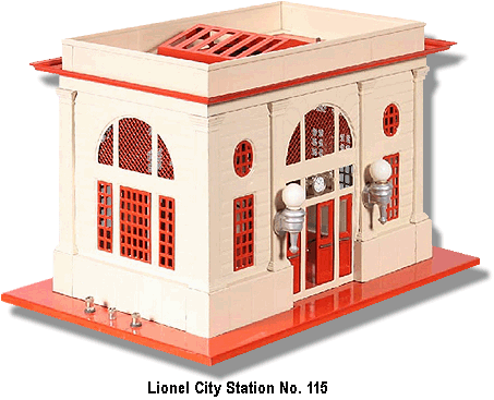
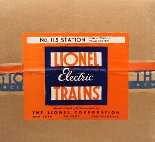
 The Lionel City Station No. 115 was carried over from pre-war production and was available from 1946 until 1949 during the Post War period. While undersized for the role of a big city station this was, none the less, a large accessory and collectors are very fond of this station. The Lionel City Station No. 115 was carried over from pre-war production and was available from 1946 until 1949 during the Post War period. While undersized for the role of a big city station this was, none the less, a large accessory and collectors are very fond of this station.

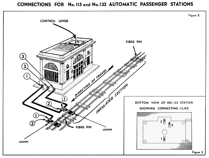
Made almost entirely of all metal components this station featured Lionel’s "Automatic Train Control." This feature allowed the automatic stopping of trains in front of the station for a set period of time before resuming. This was accomplished by insulating the center rails on the track sections in front of the station (usually two or three sections), setting the control unit on the train engine to only the forward direction, and the use of a bimetallic strip in the station that when heated would disconnect the power to the insulated center rail. The control lever for this stopping period is accessed by removing the skylight. The waiting period could then be set anywhere from no stopping to stopped for approximately one minute.

The commonly missing skylight has been reproduced and is difficult to distinguish from the original.

This station was illuminated by a No. L432 lamp and two SILVER painted sconces on the front of the station that used a specially frosted WHITE lamp No. 1442(W). Lionel’s identifying nomenclature is rubber-stamped in BLACK on the bottom of this accessory.

There were three instruction sheets that were issued during the Post War Era. The first of these, No. 115-2, was issued with DARK BLUE ink on LIGHT BLUE paper and dated 3-46 (See: No. 132). The next issues are both on WHITE paper with BLACK ink and were issued 3-49 and 3-50 and share the common wiring information with the No. 132 which was released in 1949. We’ve pictured this wiring diagram from this sheet below.

Dimensions: 13-5/8 " long, 9-1/4" wide, 8-1/2" high.
|


