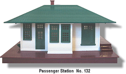
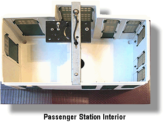
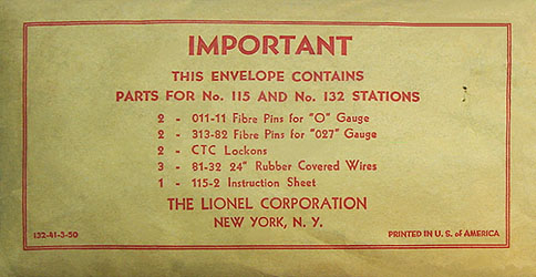
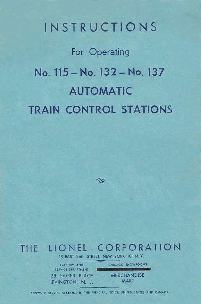
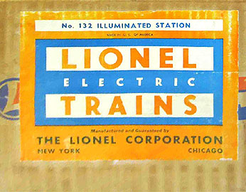
 The Passenger Station No. 132 was available beginning in 1949 and would continue to be catalogued until 1955. It would replace the No. 115 Lionel City Station in 1950. This station was illuminated by an No. L431 Lamp. Like the No. 115 before it, this station featured automatic train control that would stop a train at any insulated track section(s) that were usually located near the station. The control, that is illustrated above in the interior view, was accessed by removing the roof, and was thermostatically controled. To use this feature the locomotive’s directional unit must be set in the "forward only" position. The Passenger Station No. 132 was available beginning in 1949 and would continue to be catalogued until 1955. It would replace the No. 115 Lionel City Station in 1950. This station was illuminated by an No. L431 Lamp. Like the No. 115 before it, this station featured automatic train control that would stop a train at any insulated track section(s) that were usually located near the station. The control, that is illustrated above in the interior view, was accessed by removing the roof, and was thermostatically controled. To use this feature the locomotive’s directional unit must be set in the "forward only" position.

Electrical power was connected with three binding clips on the bottom of the station. All No. 132 Passenger Stations have a RED painted chimney on the roof. However, it is sometimes found with a GREEN painted chimney that was used on the roofs of the later issued No. 133 Passenger Station. These roofs are interchangeable, however, the No. 133 Passenger Station does not have the train control feature.
|
|
 |
